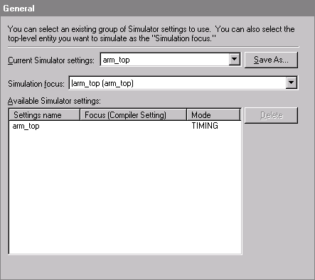
Choose Settings (Assignments menu).

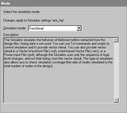
In the Category list, select Mode under Simulator Settings.
In the Simulation mode list, select Functional. A description of functional simulation appears in the Description field.

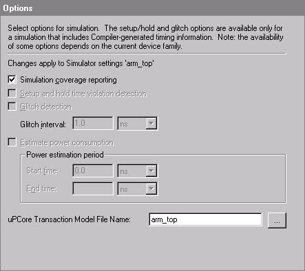
In the Category list, select Options under Simulator Settings.
Make sure Simulation coverage reporting is turned on.
In the uPCore Transaction Model File Name box, type arm_top or click Browse (...) to select the arm_top.mbus_in file. The Simulator uses this file to simulate the interactions between the Stripe-To-PLD bridge and the PLD slave.

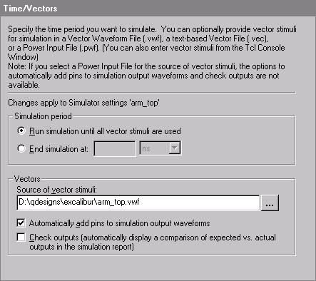
In the Category list, select Time/Vectors under Simulator Settings.
Under Simulation period, make sure Run simulation until all vector stimuli are used is selected.
Under Vectors, in the Source of vector stimuli box, type D:\qdesigns\excalibur\arm_top.vwf, or click Browse (...) to select the file. The arm_top.vwf file contains the input and output vectors required for functional simulation.
Make sure Automatically add pins to simulation output waveforms is turned on.

Click OK.